
Anti‑Tamper and Fault Injection Protection
Overview
Anti‑tamper and fault injection protection focuses on defending a system against physical, electrical, and timing‑based attacks designed to bypass security mechanisms or corrupt internal states. Attackers may manipulate voltage, clock, temperature, electromagnetic fields, or even probe internal nodes to induce faults or extract sensitive information.
This domain ensures that the system can detect, withstand, and recover from intentional disturbances.
Main Security Threats
Voltage glitching
Injecting rapid undervoltage or overvoltage pulses to corrupt logic or skip instructions.
Clock manipulation
Altering frequency, duty cycle, or injecting extra edges to desynchronize logic.
Electromagnetic fault injection (EMFI)
Using EM pulses to flip bits or disrupt timing.
Laser or optical injection
Targeting silicon regions with laser pulses to induce localized faults.
Thermal manipulation
Overheating or cooling components to alter timing or analog behavior.
Probing and invasive access
Physically accessing internal nodes, buses, or memory arrays.
Package tampering
Decapping, microprobing, or modifying the package to expose internal structures.
Side‑channel exploitation
Extracting information from power, timing, or electromagnetic emissions.
Sensor spoofing
Manipulating tamper sensors, voltage monitors, or temperature sensors to hide attacks.
Figure 1 — Fault Injection Attack Surface
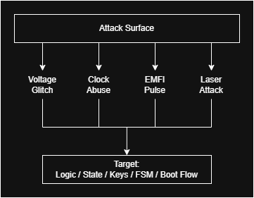
Attackers can target voltage, clock, EM, laser, or physical interfaces. Protection must cover all vectors.
Mitigation Techniques
1. Voltage and clock supervision
Continuous monitoring for undervoltage, overvoltage, glitches, and abnormal clock behavior.
2. Glitch filtering and shaping
Rejecting pulses that are too short, too fast, or inconsistent with expected behavior.
3. Redundant computation
Dual or lockstep execution paths with comparison to detect injected faults.
4. Hardened flip‑flops and synchronizers
Increasing resistance to metastability and transient faults.
5. Active tamper sensors
Detecting probing, light exposure, temperature anomalies, or package intrusion.
6. Shielding and mesh protection
Conductive meshes or sensor grids to detect physical tampering.
7. Randomized timing
Adding jitter or random delays to make fault injection less predictable.
8. Secure boot and key protection
Ensuring injected faults cannot bypass authentication or key checks.
9. Error detection and recovery
CRC, MAC, parity, rollback, and watchdog mechanisms to detect and correct corrupted states.
10. Built‑In Self‑Test (BIST)
Validating critical logic paths and sensors to detect degradation or tampering.
Figure 2 — Tamper Detection and Response Pipeline

The system monitors voltage, clock, and sensors. If an anomaly is detected, it triggers a security response.
Relationship with Safety
Safety
Deals with random electrical faults, noise, and environmental stress.
Security
Deals with intentional, targeted manipulation of the same physical phenomena.
Overlap
- Fault injection attacks mimic brown‑out, jitter, or timing faults seen in Safety.
- Voltage and clock supervision strengthen both domains.
- Redundant computation and monitoring improve resilience to both accidental and malicious faults.
