
Voter Architectures
Overview
Voter circuits are the core decision elements in redundant safety architectures such as TMR (Triple‑Modular Redundancy). Their role is to compare the outputs of multiple redundant channels and select a valid result according to a defined voting rule. Because the voter determines the final system output, its design must be robust, deterministic, and protected against becoming a single point of failure.
This page introduces the main voter types, their behavior, and their safety implications.
Majority Voter (2‑out‑of‑3)
The most common voter architecture is the 2‑out‑of‑3 majority voter, used in TMR systems. It outputs the value agreed upon by at least two of the three channels.
Characteristics:
- Masks any single‑channel fault.
- Requires three redundant inputs.
- Sensitive to common‑cause faults affecting two or more channels.
- The voter itself must be protected or replicated.
Figure 1: TMR Majority Voter
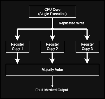
TMR majority voter. Three redundant channels provide independent copies of the same safety‑critical value. The voter selects the value agreed upon by at least two channels, masking any single‑channel fault and ensuring continuity of operation.
1‑out‑of‑2 Comparator (DMR)
Used in dual‑core lockstep systems. This is not a voter in the strict sense, but a mismatch detector.
Characteristics:
- Detects faults but does not mask them.
- Requires two redundant inputs.
- Triggers a safe reaction when outputs differ.
Triplicated Voters (TMR‑of‑TMR)
In high‑integrity systems, the voter itself may be triplicated to avoid becoming a single point of failure.
Architecture:
- Three independent majority voters.
- A second‑stage voter selects the final output.
Benefits:
- Removes the voter as a single point of failure.
- Increases diagnostic coverage.
Limitations:
- Higher area and power.
- More complex verification.
Figure 2: Triplicated Voter (TMR-of-TMR)
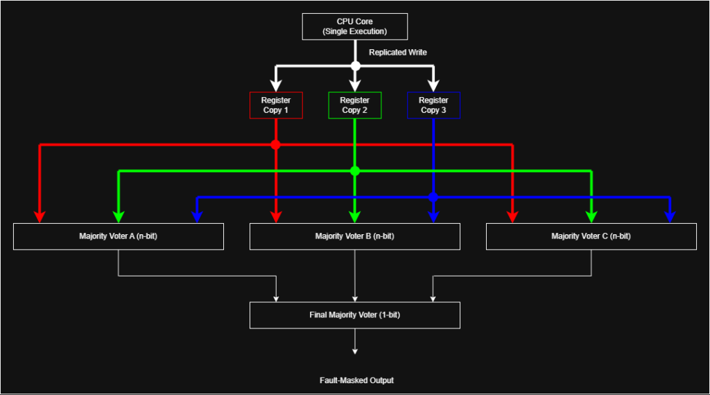
Triplicated voter architecture. Each majority voter receives the full multibit bus from the three redundant register copies. The final majority voter compares only the three 1‑bit voted results, reducing complexity and eliminating the voter as a single point of failure.
Failure Modes
Voter Stuck‑at Fault
If the voter output is stuck at 0 or 1, redundancy is defeated.
Input Corruption
If two or more channels are corrupted identically (common‑cause fault), the voter cannot recover the correct value.
Logic Design Errors
Incorrect Boolean implementation or synthesis optimizations may introduce systematic faults.
Design Considerations
- Hardened logic — use radiation‑tolerant or safety‑qualified cells.
- Physical separation — avoid placing redundant voters adjacent to each other.
- Diversity — implement voters using different logic styles or synthesis constraints.
- Formal verification — ensure correctness of the Boolean function.
