
Safety in CPU / Lockstep
Introduction
Lockstep architectures are used in safety‑critical systems to ensure that CPU computation errors are detected with extremely high diagnostic coverage. Two (or more) processor cores execute the same instructions in parallel, and their outputs are continuously compared. Any divergence indicates a fault in one of the cores or in the surrounding logic.
This page describes the safety principles, failure modes, and diagnostic mechanisms associated with lockstep CPU architectures.
Lockstep Execution Models
Lockstep can be implemented in different ways depending on performance, power, and safety requirements:
- Cycle‑by‑cycle lockstep — both cores execute the same instruction every cycle, with immediate comparison.
- Delayed lockstep — the checker core runs a few cycles behind the main core to avoid common‑cause faults.
- Dual‑core lockstep (DCLS) — two cores with a comparator and fault signaling logic.
- Triple modular redundancy (TMR) — three cores with majority voting for fault masking.
Each model offers different trade‑offs between fault detection latency, common‑cause robustness, and hardware cost.
Safety‑Relevant Failure Modes
CPU and lockstep logic can experience several types of faults:
- Transient faults — radiation‑induced bit flips in registers or pipelines.
- Permanent faults — stuck‑at or bridging faults in ALU, control logic, or register files.
- Comparator failure — the lockstep comparator becomes stuck or fails to detect mismatches.
- Common‑cause faults — both cores produce the same wrong result due to shared resources or identical disturbance.
- Clock or power anomalies — affecting both cores simultaneously.
- Instruction fetch corruption — wrong instruction delivered to both cores.
These faults can lead to incorrect computation, unsafe control decisions, or loss of system integrity.
Temporal diversity and transient faults
Delayed lockstep is particularly effective against transient faults, such as radiation‑induced bit flips, EMI bursts, or short‑duration supply disturbances. These events are brief in time and should not affect both cores at the same logical instant. By introducing a delay of one or more clock cycles between Core A and Core B, the comparator aligns Core A at time t with Core B at time t + delay. This temporal diversity reduces the probability that the same disturbance corrupts the same operation in both pipelines, improving robustness against common‑cause and time‑correlated faults.
Diagnostic Mechanisms
Safety‑critical CPUs implement multiple layers of diagnostics:
- Lockstep comparator — detects mismatches between main and checker cores.
- Error signaling module (ESM/FCCU) — centralizes CPU fault reporting and triggers safe‑state transitions.
- Instruction and data integrity checks — ECC, parity, and address monitoring.
- Clock and voltage monitoring — detect anomalies that may affect both cores.
- Self‑test mechanisms — CPU self‑test (STL), LBIST, and periodic diagnostics.
- Redundant execution paths — software redundancy or algorithmic checks.
These mechanisms ensure that CPU faults are detected quickly and reliably.
Safety Architecture Considerations
Lockstep interacts with several safety‑critical subsystems:
- Memory protection — ECC, MPU, and address checking.
- Interrupt and exception handling — ensuring deterministic and safe reactions to faults.
- Safe‑state management — defining how the system behaves after a CPU mismatch.
- Startup tests — verifying CPU integrity before enabling safety functions.
- Periodic diagnostics — maintaining coverage during operation.
The safety case must justify diagnostic coverage, fault detection latency, and common‑cause mitigation strategies.
Diagrams and examples
Figure 1: Dual‑core lockstep architecture (DMR)

Dual‑core lockstep architecture with cycle‑accurate comparison. Core A and Core B execute identical operations, and the comparator detects divergences caused by transient, permanent, or systematic faults. The fault signaling unit aggregates errors, while memory ECC and clock/power monitors mitigate common‑cause and external disturbances.
Figure 2: Comparator and fault signaling logic
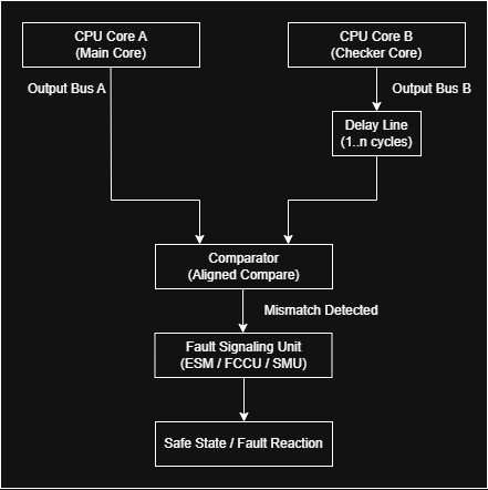
Comparator with temporal alignment. Core B outputs are delayed by 1..N cycles so that the comparator aligns Core A at time t with Core B at time t + delay, providing temporal diversity against transient and common‑cause faults.
Figure 3: Delayed lockstep timing diagram

Delayed lockstep model. Core A and Core B execute the same instruction sequence with a fixed cycle offset. The comparator realigns the pipelines at the comparison point, improving robustness against common‑cause faults while maintaining high diagnostic coverage.
Figure 4: Common‑Cause Fault Scenarios
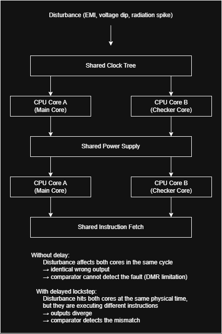
Common‑cause fault scenarios. A simultaneous disturbance (EMI, voltage dip, radiation strike) may affect both cores through shared resources such as clock, power, or instruction fetch. In cycle‑by‑cycle lockstep this produces identical wrong outputs, making the fault undetectable. In delayed lockstep, the two cores are offset in time, so the same disturbance affects different operations, making the mismatch detectable.
Figure 5: TMR Majority Voter

Triple‑modular redundancy (TMR). Three independent cores execute the same operations, and a majority voter masks single‑core faults by selecting the value agreed upon by at least two cores. Unlike dual‑core lockstep, which provides fault detection, TMR provides fault masking — a distinction many readers overlook.
