
DFT Overview
Introduction
Design‑for‑Testability (DFT) introduces architectural features that make internal logic controllable and observable during test.
Without DFT, most internal faults remain hidden because internal nodes cannot be accessed directly from I/O pins.
DFT provides the structural foundation for manufacturing test, in‑field diagnostics, and safety‑critical fault detection.
Why DFT Exists
Modern digital systems contain millions of internal nodes.
DFT ensures that these nodes can be:
- Controlled — driven to known logic values
- Observed — captured and shifted out for analysis
- Isolated — faults can be localized to specific regions
- Tested deterministically — repeatable behavior across devices and conditions
These properties enable high fault coverage, predictable diagnostics, and measurable safety metrics.
Core DFT Mechanisms
DFT relies on architectural techniques that expose internal logic for structural testing:
Scan Architecture
Transforms flip‑flops into a shift register, enabling full internal visibility.
Test Points
Improve controllability and observability in hard‑to‑reach logic regions.
Boundary Scan (IEEE 1149.1)
Provides standardized access to I/O pins and internal registers.
Clock Control
Enables deterministic capture and shift operations.
Compression Logic
Reduces test time and pattern volume.
Built‑In Self‑Test (BIST)
Enables autonomous test generation and response analysis.
Together, these mechanisms form the backbone of digital testability.
DFT and ATPG
Automatic Test Pattern Generation (ATPG) uses the DFT infrastructure to apply deterministic patterns targeting structural fault models such as:
- stuck‑at
- transition
- bridging
- path delay
- open/short defects
DFT provides the controllability and observability required for ATPG to achieve high fault coverage.
DFT and Functional Safety
DFT contributes directly to safety‑critical systems by enabling:
- structural fault detection
- diagnostic coverage measurement
- startup and periodic self‑tests (LBIST/MBIST)
- fault isolation and root‑cause analysis
- FIT budgeting and FMEDA justification
DFT is a foundational enabler for safety‑certifiable architectures.
Diagrams
Figure 1: DFT Landscape
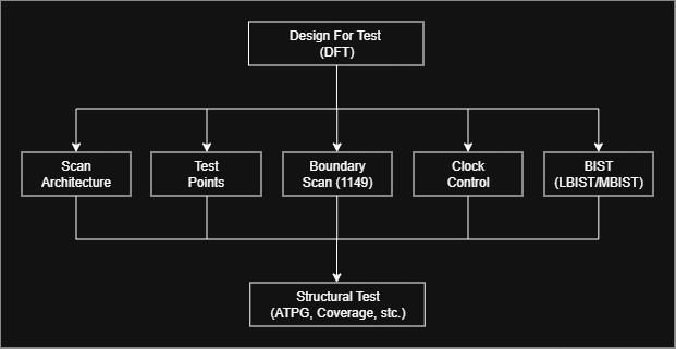
This diagram summarizes the main architectural mechanisms that enable structural testability in digital systems.
Scan architecture, test points, boundary scan, clock control, and BIST collectively provide the controllability and observability required for ATPG, fault coverage, and in‑field diagnostics.
Figure 2: DFT, Structural Test, and Functional Safety
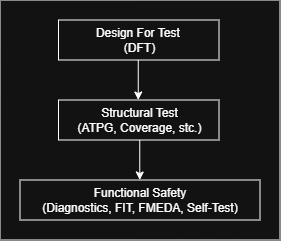
DFT provides the architectural hooks that enable structural test.
Structural test (ATPG, fault models, coverage) delivers the diagnostic capability required by safety‑critical systems.
Functional Safety builds on DFT to achieve diagnostic coverage, periodic self‑tests, FIT budgeting, and FMEDA justification.
Figure 3: Controllability / Observability
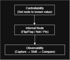
DFT enables internal nodes to be driven to known logic values (controllability) and later captured and shifted out for analysis (observability).
This drive–propagate–capture sequence is the foundation of structural testing, ATPG, and diagnostic coverage.
Figure 4: DFT → ATPG → Fault Coverage
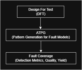
DFT provides the controllability and observability required for ATPG to generate deterministic test patterns targeting structural fault models.
The effectiveness of these patterns is measured through fault coverage, which quantifies the percentage of detectable defects and directly impacts product quality and yield.
