
Safety in Scrambling & Whitening
Overview
Scrambling and whitening transform data into a pseudo‑random sequence to improve spectral distribution, reduce EMI, and prevent long runs of identical bits. In safety‑critical systems, scramblers also act as diagnostic amplifiers: they multiply certain classes of errors, making faults easier to detect.
Safety analysis focuses on:
- error multiplication
- lock‑up conditions
- LFSR‑based failure modes
- burst propagation
- symbol‑level anomaly detection
Scrambling is not just a signal‑conditioning technique — it is a safety‑relevant transformation layer.
Why Scrambling Matters for Safety
Scramblers influence:
- transition density
- run‑length
- error propagation
- detectability of upstream faults
- robustness against SEUs
- diagnostic coverage
A malfunctioning scrambler can hide faults or amplify them unpredictably.
Safety‑Relevant Concepts in Scrambling & Whitening
1. Error Multiplication
Scramblers intentionally spread bit errors across multiple positions. Safety relevance:
- improves detectability
- prevents silent corruption
- increases diagnostic coverage
Figure 2 — Error Propagation in Symbol Streams

A single corrupted symbol can cause invalid symbols, loss of alignment, and cascaded decoding errors.
2. LFSR‑Based Scrambler Behavior
Most scramblers use LFSRs. Safety relevance:
- LFSR lock‑up (all‑zero state)
- wrong polynomial
- incorrect seeding
- stuck taps
- broken XOR feedback
These faults reduce randomness and may hide upstream anomalies.
Figure 12 — Bit‑Flip Fault Detection Path
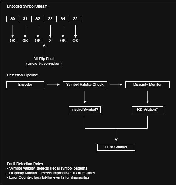
Bit‑flip faults alter individual encoded symbols. Symbol‑validity and disparity checks detect illegal patterns or impossible transitions.
3. Burst Error Propagation
Scramblers convert localized faults into bursts. This is beneficial for safety because:
- bursts are easier to detect
- CRC and FEC are optimized for burst detection
- silent corruption becomes unlikely
Figure 23 — SEU Impact on Symbol Stream

SEUs introduce transient bit‑flips that corrupt individual symbols or disrupt symbol boundaries. Line‑coding monitors detect the resulting invalid patterns or alignment loss.
4. Whitening and Spectral Uniformity
Whitening ensures:
- balanced 1/0 distribution
- stable transition density
- predictable spectral shape
Safety relevance:
- biased sequences indicate faults
- whitening failure may break CDR
- spectral anomalies reveal upstream corruption
Figure 10 — Clock Instability Effects

Misalignment caused by jitter, SEUs, or run‑length violations leads to cascaded invalid decodes.
Failure Modes Specific to Scrambling & Whitening
- LFSR stuck‑at (all‑zero or illegal state)
- wrong polynomial
- incorrect seed
- broken feedback path
- whitening disabled or bypassed
- error multiplication collapse
- biased output sequences
- SEU‑induced corruption of scrambler state
Figure 13 — Upstream I/O Fault Effects

Upstream I/O faults such as stuck‑at, open, or metastability corrupt the raw data before encoding. Line‑coding monitors detect the resulting anomalies.
Diagnostic Mechanisms
1. Scrambler Self‑Test
Short known sequences verify:
- correct polynomial
- correct seeding
- ability to traverse expected states
2. Transition‑Density Monitoring
Detects whitening failures.
3. Run‑Length Monitoring
Detects scrambler lock‑up or bias.
4. Symbol‑Validity Checks
Detect illegal patterns after descrambling.
Figure 7 — Error Counters Architecture

Each safety‑relevant event increments a dedicated counter, enabling threshold‑based alarms and long‑term monitoring.
Architectural Safety Mechanisms
1. Redundant Scramblers (Lockstep)
Two scramblers operate in parallel. A comparator detects:
- LFSR divergence
- stuck taps
- incorrect feedback
- SEU‑induced corruption
Figure 8 — Encoder / Decoder Redundancy (Lockstep)

Dual encoders operate in lockstep, producing two independent encoded streams. A comparator checks them cycle‑by‑cycle.
2. Multi‑Layer Integrity Stack
Scrambling works together with:
- line coding
- CRC
- FEC
- PHY monitoring
Figure 24 — Multi‑Layer Integrity Stack

Integrity is enforced across multiple layers: PHY, line coding, CRC, and FEC form a robust protection strategy.
Fault Isolation and Safety Coverage
Scrambling helps isolate faults by amplifying anomalies.
Figure 18 — Fault Isolation Flow

Faults propagate upward through line‑coding monitors, where anomalies are detected and logged.
Figure 19 — Safety Coverage Map

Symbol‑validity checks, disparity monitoring, run‑length control, and alignment supervision feed into error counters.
Safety Event Analysis
Scrambling affects the timing and visibility of safety events.
Figure 21 — Safety Event Timeline

The safety event timeline illustrates how anomalies emerge, propagate, and are detected by monitoring blocks.
Fault Injection and Validation
Scrambler fault injection validates:
- error multiplication
- detection paths
- diagnostic coverage
Figure 22 — Encoder Fault Injection Example

Fault injection produces controlled anomalies that validate the monitoring chain.
