
Safety in DC‑Balance & Transition‑Density Mechanisms
Overview
DC‑balance and transition‑density mechanisms ensure that the transmitted bitstream maintains stable electrical characteristics and provides sufficient transitions for clock recovery. In safety‑critical systems, these properties are essential for:
- maintaining synchronization
- preventing baseline wander
- ensuring robust CDR (Clock Data Recovery)
- exposing upstream faults through bias or run‑length anomalies
Faults affecting DC balance or transition density can silently degrade link integrity, making their monitoring a key safety requirement.
Why DC‑Balance Matters for Safety
DC‑balance ensures that the average number of 1s and 0s remains stable over time. Safety relevance:
- prevents baseline wander
- avoids threshold drift
- ensures correct sampling
- reveals encoder faults through bias anomalies
Figure 4 — Running Disparity Evolution

Running disparity monitoring verifies that each transmitted symbol maintains the correct polarity balance. Illegal transitions or impossible disparity combinations reveal encoder faults or corrupted symbol boundaries.
Why Transition Density Matters for Safety
Transition density ensures that the receiver’s CDR has enough edges to maintain lock. Low transition density can cause:
- loss of lock
- increased jitter
- symbol boundary drift
- silent data corruption
Figure 10 — Clock Instability Effects

Misalignment caused by jitter, SEUs, or run‑length violations leads to cascaded invalid decodes. Alignment monitoring detects boundary loss and triggers recovery using comma patterns or sync markers.
Safety‑Relevant Concepts
1. Run‑Length Limiting
Run‑length limiting prevents long sequences of identical bits, which can break CDR and hide bit errors.
Figure 3 — Run‑Length Monitoring

The run‑length monitor detects when consecutive identical bits exceed the maximum allowed sequence length. Violations indicate encoder faults, upstream I/O issues, or signal‑integrity degradation.
2. Bias and Drift Detection
Bias faults occur when the bitstream contains more 1s than 0s (or vice versa). Safety relevance:
- indicates upstream corruption
- reveals scrambler or encoder malfunction
- exposes stuck‑at or open I/O faults
Figure 13 — Upstream I/O Fault Effects

Upstream I/O faults such as stuck‑at, open, or metastability corrupt the raw data before encoding. Line‑coding monitors detect the resulting anomalies.
3. Transition‑Density Collapse
Transition‑density collapse is one of the most dangerous failure modes because it can cause:
- CDR unlock
- symbol misalignment
- cascaded invalid decodes
- silent corruption if undetected
Figure 9 — Decoder Alignment Fault Propagation

Misalignment caused by jitter, SEUs, or run‑length violations leads to cascaded invalid decodes. Alignment monitoring detects boundary loss and triggers recovery.
4. Error Propagation and Containment
DC‑balance and transition‑density mechanisms influence how errors propagate:
- high transition density → localized errors
- low transition density → cascaded misalignment
- DC imbalance → threshold drift → burst errors
Figure 2 — Error Propagation in Symbol Streams

A single corrupted symbol can cause invalid symbols, loss of alignment, and cascaded decoding errors.
Failure Modes Specific to DC‑Balance & Transition‑Density
- stuck‑at sequences (all‑zeros, all‑ones)
- biased patterns
- run‑length violations
- transition‑density collapse
- DC drift
- incorrect disparity evolution
- loss of alignment due to insufficient transitions
Figure 12 — Bit‑Flip Fault Detection Path

Bit‑flip faults alter individual encoded symbols. Symbol‑validity and disparity checks detect illegal patterns or impossible transitions.
Diagnostic Mechanisms
1. Disparity Monitoring
Detects DC‑balance faults and impossible transitions.
2. Transition‑Density Monitoring
Detects whitening or encoder failures.
3. Run‑Length Counters
Detect scrambler lock‑up or bias.
4. Alignment Supervision
Detects boundary loss caused by low transition density.
Figure 7 — Error Counters Architecture
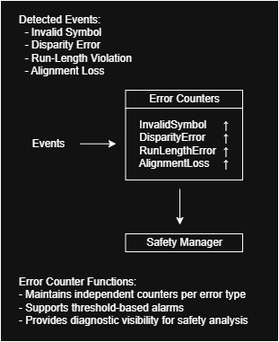
Each safety‑relevant event increments a dedicated counter, enabling threshold‑based alarms and long‑term monitoring.
Architectural Safety Mechanisms
1. Multi‑Layer Integrity Stack
DC‑balance and transition‑density mechanisms work together with:
- line coding
- scrambling
- CRC
- FEC
- PHY monitoring
Figure 24 — Multi‑Layer Integrity Stack
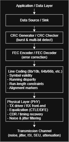
Integrity is enforced across multiple layers: PHY, line coding, CRC, and FEC form a robust protection strategy.
2. Fault Isolation and Coverage
DC‑balance and transition‑density anomalies help isolate faults across layers.
Figure 18 — Fault Isolation Flow
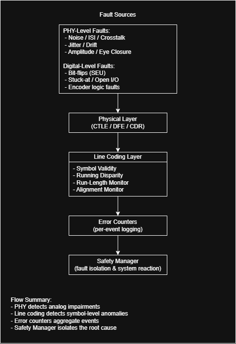
Faults propagate upward through line‑coding monitors, where anomalies are detected and logged.
Figure 19 — Safety Coverage Map

Symbol‑validity checks, disparity monitoring, run‑length control, and alignment supervision feed into error counters.
Safety Event Timing and Reaction
Transition‑density and DC‑balance faults often manifest gradually. Monitoring their evolution over time is essential.
Figure 21 — Safety Event Timeline

The safety event timeline illustrates how anomalies emerge, propagate, and are detected by monitoring blocks.
Safety vs. Performance Trade‑offs
High‑efficiency line codes reduce redundancy, increasing reliance on:
- external CRC
- FEC
- PHY‑level monitoring
Figure 28 — Safety vs. Performance Trade‑off Map
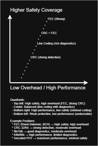
Different line‑coding and protection schemes balance safety coverage against bandwidth efficiency and latency.
